Introduction:
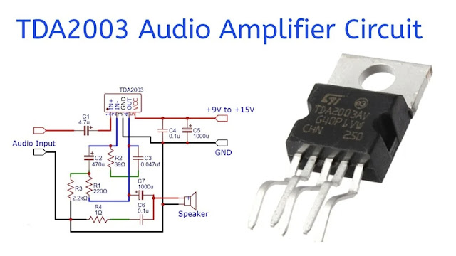
The TDA2003 is a versatile 10W audio amplifier IC commonly used in car radios and small audio systems. It features low harmonic distortion, short-circuit protection, and thermal shutdown. This circuit uses the TDA2003 to amplify audio signals with minimal external components, making it compact and cost-effective.
The input signal is fed through a DC-blocking capacitor, and the output drives speakers ranging from 2Ω to 8Ω, delivering up to 10W of output power. Various capacitors and resistors in the circuit stabilize the amplifier and filter noise, while the power supply can range from +8V to +18V. The circuit is ideal for DIY audio projects or low-power audio amplification applications.
Component Details:
- TDA2003
- Capacitor 1000uf, 470uf, 4.7uf, 0.1uf, 0.047uf
- Resistor 2.2kΩ, 220Ω
- Speaker 8Ω
- Audio Input
- Power Supply +8V to +18V
TDA2003 Pinout:
The TDA2003 is a monolithic integrated circuit designed primarily for use in car radio systems as a low-frequency class AB audio amplifier. It offers high performance in terms of audio quality, reliability, and protection features.
TDA2003 Pin Configuration:
- Pin 1 (Non-Inverting Input): This pin receives the audio input signal. The signal is typically fed through a capacitor to block DC.
- Pin 2 (Inverting Input): This pin is usually connected to ground through a capacitor or part of a feedback loop, depending on the circuit design.
- Pin 3 (Ground): Ground pin of the IC, connected to the circuit's ground.
- Pin 4 (Output): The amplified audio signal is output from this pin, which is connected to the speaker through a coupling capacitor.
- Pin 5 (Vcc): The power supply pin. It accepts a voltage from +8V to +18V, typically from a car battery or other power source.
Simplified Pinout:
- Pin 1: Non-Inverting Input (+)
- Pin 2: Inverting Input (−)
- Pin 3: Ground
- Pin 4: Output
- Pin 5: Supply Voltage (+Vcc)
Key Features:
- Output Power: Capable of delivering up to 10W of audio output to a speaker when powered with an 18V supply and using a 2Ω load. At lower voltages, it can still output around 6W with a 4Ω speaker.
- Operating Voltage: Works in a wide voltage range from 8V to 18V, making it suitable for various audio applications, including car radio amplifiers.
- Low Harmonic Distortion: Delivers clear audio output with minimal distortion and low noise.
- Short-Circuit Protection: Automatically protects the circuit from short circuits, ensuring safe operation under accidental fault conditions.
- Thermal Shutdown: Includes thermal protection, automatically turning off the IC when it overheats, preventing damage due to excessive temperature.
- High Current Capability: It can handle peak currents of up to 3.5A, allowing it to drive lower-impedance speakers effectively.
- Low External Components: Requires only a few external resistors and capacitors, simplifying the design and reducing component count.
Circuit Diagram:
Circuit Working:
This is a schematic for a 10W audio amplifier using the TDA2003 integrated circuit. The TDA2003 is a popular amplifier IC commonly used in low-power audio applications, especially in car radio systems. Here’s a breakdown of the circuit components and their functions:
Key Components:
- TDA2003 (IC1): This is the main amplifier IC capable of delivering up to 10W output.
- Input (C1 - 4.7µF): The input signal is fed through capacitor C1 (which blocks DC) and is sent to pin 1 of the TDA2003.
- C2 (470µF): Provides power supply filtering and stabilization between pins 2 and 3.
- C6 (0.1µF) and C7 (1000µF): Power supply decoupling capacitors; C7 is for large voltage variations, while C6 filters high-frequency noise.
- R1 (39Ω), C3 (0.039µF): Compensation network for the feedback loop, which ensures stability of the amplifier.
- R2 (220Ω), R3 (2.2Ω): Biasing and gain control resistors for the amplifier.
- C4 (1000µF): Coupling capacitor, which blocks DC from reaching the speaker (SP1) and passes the amplified AC audio signal.
- C5 (0.1µF): Output filter capacitor, reducing high-frequency noise at the speaker output.
- R4 (1Ω): Additional resistance in series with the speaker to improve stability.
- Speaker (SP1): The audio output device, connected between the output capacitor C4 and ground.
Power Supply:
- The amplifier is powered by a single supply voltage, labeled as +VS, which can range from +8V to +18V.
Output:
- The output can drive speakers ranging from 2Ω to 8Ω, producing approximately 10W of audio power depending on the supply voltage and load impedance.
This circuit is simple and reliable for use in basic audio amplifier applications such as small audio systems or DIY audio projects.
Applications:
- Car Radio Amplifiers: Most commonly used in car audio systems to drive small speakers or subwoofers.
- Portable Audio Systems: Suitable for battery-operated or low-power speaker systems.
- DIY Audio Projects: Popular in hobbyist audio amplifier designs due to its ease of use.
- Television Audio Systems: It can also be used in TV audio circuits to amplify sound output in smaller or older television models, enhancing audio quality.
- Alarm Systems: The TDA2003 can be used to amplify alarm signals in security systems, ensuring loud, clear audio output when an alarm is triggered.
The TDA2003 can be used to amplify alarm signals in security systems, ensuring loud, clear audio output when an alarm is triggered.


