
Introduction:
A DC motor speed control circuit allows precise regulation of motor speed using a PWM (Pulse Width Modulation) technique. This circuit is based on the NE555 timer IC, which generates a variable PWM signal to control the power delivered to the motor. The IRF540 MOSFET acts as a switch, efficiently handling motor current. A 100K potentiometer adjusts the PWM duty cycle, enabling speed variation.
Additional components, such as resistors, capacitors, and a diode, help stabilize the circuit and protect against voltage spikes. The 1N4001 diode safeguards against back EMF from the motor. This design is ideal for applications like robotics, fans, and small electric vehicles. Simple, cost-effective, and efficient, this circuit provides smooth motor speed control, improving performance while minimizing power loss.
Component Details:
| S.no | Components | Value | Qty. |
|---|---|---|---|
| 1. | Time Ic | NE555 | 1 |
| 2. | MOSFET | IRF540n | 1 |
| 3. | Resistor | 47K, 10K, 560Ω | 1,1,1 |
| 4. | Variable Resistor | 100K | 1 |
| 5. | Capacitor | 0.47uf, 1000uf | 1,1 |
| 6. | Diode | 1N4001 | 1 |
| 7. | Motor | 12V | 1 |
| 8. | Power Supply | 12V Dc | 1 |
IRF540N Pin Configuration:
- Gate (G) – Pin 1: Controls the MOSFET switching by applying voltage.
- Drain (D) – Pin 2: The main current flows from drain to source when the MOSFET is turned ON.
- Source (S) – Pin 3: The reference point for the current flow.
.jpg)
NE555 Pinout:
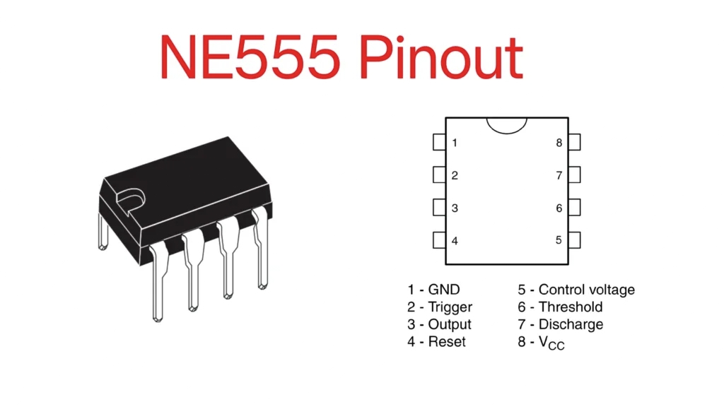
NE555 Pin Configuration:
- GND (Ground) – Pin 1: Connect to the negative supply (0V).
- Trigger – Pin 2: Activates the timer when voltage drops below 1/3 of Vcc.
- Output – Pin 3: Provides the output signal (high/low).
- Reset – Pin 4: Resets the timer when connected to ground (active-low).
- Control Voltage – Pin 5: Adjusts the threshold voltage (typically left unused).
- Threshold – Pin 6: Monitors the capacitor voltage to control timing.
- Discharge – Pin 7: Discharges the timing capacitor.
- Vcc – Pin 8: Connect to the positive supply (typically 5V-15V).
Circuit Diagram:

Working Explain:
Key Components and Their Functions:
- NE555 Timer (U1) – Generates the PWM signal to control the motor speed.
- IRF540 MOSFET (Q1) – Acts as a switch to drive the motor.
- Resistors (R1, R2, R3) – Define the timing and control characteristics of the 555 timer.
- Capacitors (C1, C2) – Used for timing and noise filtering.
- Diode (D1, 1N4001) – Protects the circuit from back EMF generated by the motor.
- Potentiometer (100K ohm) – Adjusts the duty cycle of the PWM signal, thereby controlling motor speed.
Working Principle:
- The 555 timer operates in astable mode to generate a PWM signal.
- The potentiometer (100K) allows duty cycle adjustment, which changes the motor speed.
- The MOSFET (IRF540) switches the motor ON and OFF rapidly based on the PWM signal.
- The diode (1N4001) protects the circuit from voltage spikes when the motor turns off.
- C2 (1000uF) provides power smoothing to stabilize the circuit.
Motor Speed Control:
- Higher duty cycle → More power to motor → Higher speed
- Lower duty cycle → Less power to motor → Lower speed
Applications:
Robotics 🤖
- Used in robots for precise speed control of motors in robotic arms, wheeled robots, and automation projects.
Electric Fans & Blowers 🌬️
- Controls the speed of cooling fans, exhaust fans, and small blowers in electronics and appliances.
Conveyor Belt Systems 🏭
- Adjusts the speed of conveyor belts in industrial automation and material handling.
Automotive Applications 🚗
- Used in electric car wipers, power window systems, and ventilation fans for variable speed control.
DIY & Educational Projects 📚
- Common in hobby electronics and student projects for learning PWM speed control techniques.